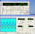
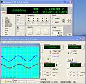
Level_set_source
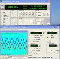
Level_set_source_minus_20dB
Source_minus_20dB

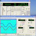
Tape_az_OK
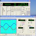
Tape_az_1left

Tape_az_2left

Tape_az_1right
Tape_az_2right
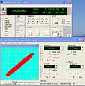
Tape_az_OK_XY
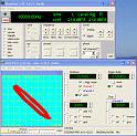
Tape_az_0.5_left_XY
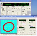
Tape_az_1_left_XY
|
Level_set_source |
Level_set_source_minus_20dB |
Source_minus_20dB |
Tape_az_OK |
Tape_az_1left |
Tape_az_2left |
|
Tape_az_1right |
Tape_az_2right |
Tape_az_OK_XY |
Tape_az_0.5_left_XY |
Tape_az_1_left_XY |