Parametric distortion
compensation in FETs
or
How to build a Solid-State
Triode.
When a JFET compared to a valve it is usually compared to a pentode, because of FET's high output impedance - both devices behave like current sources. Vacuum triode however has low output impedance and low gain. On the other hand a triode has got an advantage of a more linear transfer characteristic into a high-impedance load - due to a linearising effect of the internal parametric compensation - when the anode current is reduced the anode voltage rises and compensates the reduction in the transconductance. This makes the resulting transfer characteristic much more linear, reducing the distortion.
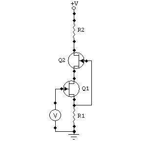
I found, that in the circuit configuration shown on Figure 1 it is possible to substantially linearise the transfer characteristic of a FET by applying the same approach. This cascode circuit is well known for many years (1) and usually used to increase the output impedance of the FET and reduce the Miller effect. For that purpose the "upper" FET is commonly chosen so it's Vgs for the given current is higher than the knee of the "lower" FET output characteristic, providing maximum gain and output impedance.
 Figure
1
Figure
1
However if the "upper" FET is selected so that the "lower" FET drain voltage is below the "knee", it is possible for a certain combination of both FET's parameters to make the "lower" FET essentially a solid-state triode, linearising the transfer characteristic in the same fashion as in a vacuum triode. Increase in the drain current due to the change in the input voltage results in the drain voltage drop, reducing the transconductance and straightening the transfer characteristic. As illustrated in Figures 2 and 3 the distortion reduction could be substantial. In both graphs the input voltage is 100 mV RMS. Figure 2 shows the distortion spectrum if Q2 is shorted (HD2 = 0.06%), Figure 3 - with a cascode (HD2 = 0.007%). As you may see, the 2-nd harmonic is almost 18 dB lower and at the same time the gain of the circuit reduced only by 0.7 dB.
Figure 2
Figure 3
It is also necessary to take care of a thermal stability in this circuit. It is possible to select FETs that would give only a small change in the compensated distortion levels over temperature. I will not go here into details of FETs used and selection criteria applied for obvious reasons. However this method of linearisation does work well enough to be implemented into useful circuits - A.N.T. Audio "Amber" headphone amplifier is one example of such implementation.
Literature: 1) The Art of Electronics, P Horowitz and W Hill, Second Edition, page 129.
Ó2004 Alex Nikitin
London, UK